Telephone Wire: The Basics of Phone Line Wiring
There’s a widely held misconception that the average person can’t understand telephone wire basics, and phone line wiring is an impossible feat for the many. The fact is small phone line wiring jobs in your house or small business can be much easier than you’d expect, and easier than shelling out exorbitant hourly fees to the phone company. If you can figure out how to wire speakers for your new stereo, you can easily wire your home or small office for your new phone system.

Wires, plugs, and the network interface
The basics of phone line wiring is pretty easy to understand. Most telephone wire are one or more twisted pairs of copper wire. The most common type is the 4-strand (2 twisted pair). This consists of red and green wires, which makes a pair, and yellow and black wires, which makes the other pair.
One telephone wire line needs only two wires. Therefore, it follows that a 4-strand telephone wire can carry two separate phone lines. The twisting keeps the lines from interfering with each other. IF you need to run more lines than just two, you may just want to use a 6-stand or higher. Telephone wire comes in two gauges, 22 gauge and 24 gauge; 24 gauge is today’s standard.
There are two types of common modular plugs; the RJ-11 and RJ-14. The most common is the RJ-11, which uses only two of the telephone wires in a four (or more) strand wire. This is the same kind of plug that you use to plug your telephone into the wall: a 1-line plug. The RJ-14 uses four wires and it’s used to handle two lines, or 2-line phones.
The First Step
The first step to a small telephone wire job is to figure out what the phone company has left you to work with. What kind of network interface do you have? They’ve probably left you with either a punchdown block, or a network interface box. If there is a punchdown block, and you can’t get the phone company to install a modular jack for each Plain Old Telephone Service (POTS) or Central Office (CO) line, then you’ll need a punchdown tool to connect your inside telephone wire to the interface. Most new installations consist of a network interface box. This has modular test jacks (where you can plug a phone in to see if the phone line is live) and a terminal strip from which you run your internal telephone wire.
Phone Line Wiring
From the network interface, you want to plan how you want the wiring in your location to be. The star (or homerun) method is the most common method of telephone wiring. Each extension or phone jack is run directly from the network interface or phone system if you’re installing one. The other type of wiring is called the series (or loop) method. In this method 1-line telephone wire links all of the extensions in a series. This loop method is not widely used anymore. As with the old type of Christmas lights, if one goes out, they all go out.
Using the star method, you’re obviously going to have to have a few wires coming from your network interface, as you’ll have one wire for each of your plugs. You may want to simplify the wiring and cut your wire costs by having few of the wires carry more than one line or extension.
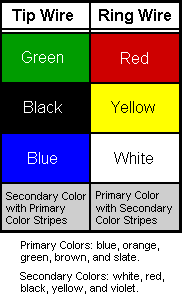
Take a 2-line installation, as an example. Each pair that comprises each of your POTS lines should be labeled. See the telephone wiring diagram below
One of the wires of your POTS line is called the tip wire, and the other is the ring wire. There are quite a few possible combinations of colors that could make up your pair. In order to connect your line to a modular jack, you need to connect the tip wire of the POTS line to the tip wire of the jack, and the ring wire of the POTS line to the ring wire of the jack.
In a modular jack, you have red/green and yellow/black. Most of the time, you only use the red/green pair. The green wire is the tip, and the red wire is the ring. Using the chart, figure out which of the POTS wires is the ring and which is the tip, and connect them appropriately.
If you are not using a phone system and just want to connect your phone jacks directly to the POTS lines, all you need to do is run wire from the network interface to your extension jacks. This works the same way when you're connecting the extension jacks of your phone system to your extensions. Just connect the correct colors to run the wire. Again, connect tip to tip and ring to ring. As long as you’re following the tip-to-tip rule, the fact that you’re connecting a white wire with brown stripes to a green wire, and a brown wire with white stripes to a red wire shouldn't be confusing.
Remember that in order to reduce the work and materials, you may run two or more lines within one telephone wire. At the end of the wire, you can break out the two lines using an adapter, which allows you to connect line 1 to an RJ-11 plug and line 2 to another RJ-11 plug; or if you have a 2-line phone, you can just plug an RJ-14 plug into the phone.
If you are using a small PBX or phone system, most likely the POTS lines (commonly called trunk lines) are connected to the system using RJ-11 plugs. If your network interface terminates with a modular jack, then the job is simple: just connect the phone system using RJ-11 plugs. If your network interface has a terminal strip (a place where the pairs that comprise each POTS line terminate at a junction where you directly connect the colored wires), then you would need to either connect the lines directly to the PBX, or connect a modular jack to each of the POTS lines on the strip. Then, to wire your phone jacks, you follow the same procedure as noted above for connecting POTS lines directly to phone jacks.
For your reference, the telephone wiring diagram below.